The computer networks are a collection of interconnected devices, such as computers, servers, printers, routers, and switches, that communicate with each other to share resources, information, entertainment and all kinds of services. These can be as simple as a few devices connected in a home or office setting, or as complex as global networks spanning multiple continents.
Networks Basic Concepts
A host is any computing device connected to a network. Therefore, a local host refers to what is in front of you, such as your macOS workstation. A remote host refers to some other computing device on the network or accessible beyond the network.
Each host on the network fulfills a specific function. A remote computer called a web server stores the files that make up a website. The web server uses server programs to store and share data. So the role of web server is to provide access to websites.
When you access a website, your web browser (probably Mozilla Firefox, Google Chrome, Safari, or Microsoft Edge) asks the web server to share the web page files and then display them. That is the role of the local host in this example. The remote computer that serves the website is a server.
Any computer that runs a sharing program is, by definition, a server. The best example of computer networks is the Internet, which consists of millions of computers located in different parts of the planet basically interconnected to share information and resources.
But we don’t need the Internet to share things. We can have a small home network made up of two computers running Windows and sharing a printer. That computer assumes the function of print server.
No matter how big the network is, we use it to share and access things. These things can be web pages, videos, printers, folders, emails, music. What you can share and access is limited only by your ability to find a server program capable of sharing it and a client program that can access it.
Networks Technology
Most networks have one or more client machines, devices that request information or services, and a server, the machine that hosts and shares the data. Both clients and servers need network interface controllers (NICs) that define or label the machine on the network.
A NIC also splits files into smaller data units for sending over the network and reassembles the units it receives into complete files. You also need some means to deliver the data units between two or more devices; This is usually a wire that can carry electrical impulses; sometimes it is radio waves or other wireless methods.
Finally, a computer’s operating system must be able to communicate with its own network hardware and with other machines on the network. A NIC is also known as a network expansion card or simply a network card. Nowadays it is common for every motherboard to have a built-in network function.
Frames and NICs
Data moves from one device to another in discrete chunks called frames. NICs create and process frames, these must contain some type of data check to verify that the data was received in good order.
To create a successful network, you need the sending and receiving devices to use the same network technology. Over the years, many hardware protocols have come and gone, but today only one hardware protocol dominates the modern computing landscape: Ethernet. Ethernet was developed for wired networks, but even wireless networks use Ethernet as the basis for their signals. To understand networking, we must understand Ethernet.
Networks Ethernet
Ethernet is a local area networking (LAN) standard that defines how devices on a network communicate with each other. It uses copper cables or optical fibers to transmit data at speeds ranging from 10 Mbps to several Gbps. Ethernet is a technology widely used in business and home environments to connect computers, printers, network devices, and other equipment together. Furthermore, it is one of the fundamental technologies in the Internet infrastructure.
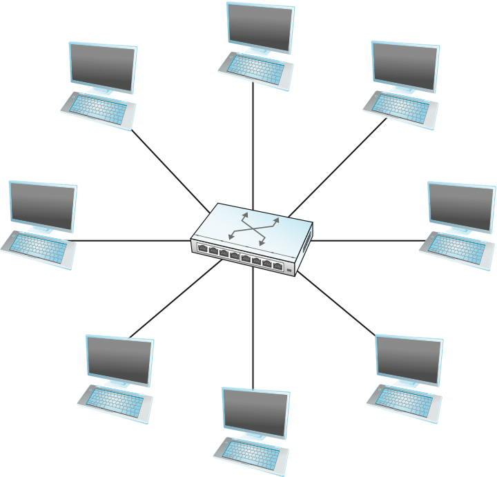
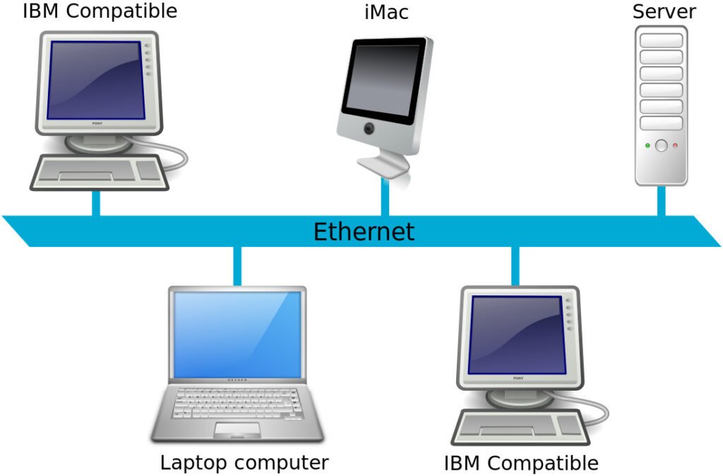
All networks technologies, collectively called Ethernet, use a star bus topology and connect via a type of cable called unshielded twisted pair (UTP).
Networks Ethernet Star Bus
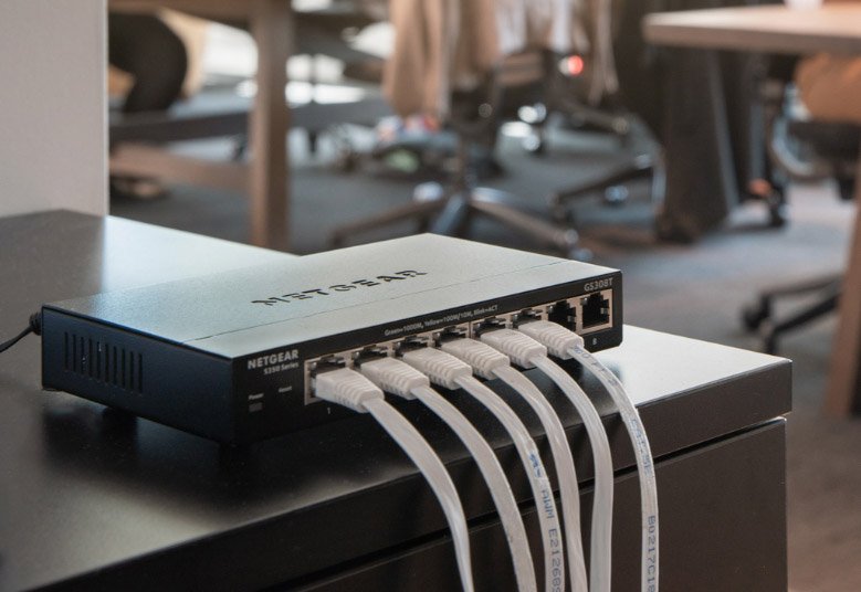
In all Ethernet networks, each individual host connects to a central box. Each system connects to this box using cables to special ports. This design, which resembles a star, is called a star bus topology.
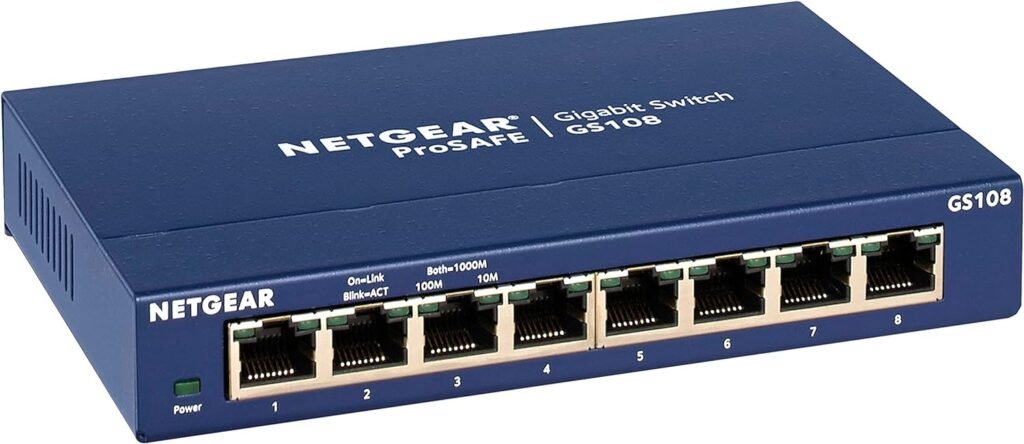
The central box called a switch provides a common connection point for network devices. Switches can have a wide variety of ports. Most consumer-grade switches have 4 or 8 ports, but enterprise-grade switches can have 32 or more ports.
Early Ethernet networks used a hub. A switch is a much superior version of a hub and replaced hubs in the 2000s.
Although they look the same and functionally do the same job, they do it differently. Basically, hubs were dumb repeaters: anything sent to one port automatically went out through all other connected ports.
Switches are smart repeaters: they memorize the media access control (MAC) addresses of all connected devices and only send repeat signals to the correct host. This makes switched networks much faster than hub networks.
A switch makes each port its own independent network. Each system can use all the bandwidth. Once switches became affordable, hubs disappeared.
In most cable types, physical Ethernet lengths are limited to 100 meters or less. You cannot use a splitter to split a cable segment into two or more connections with an Ethernet network that uses this star bus topology. Doing so prevents the switch from recognizing which host is sending or receiving a signal, and no host connected to a split segment will be able to communicate.
Unshielded Twisted Pair Cable (UTP Cable)
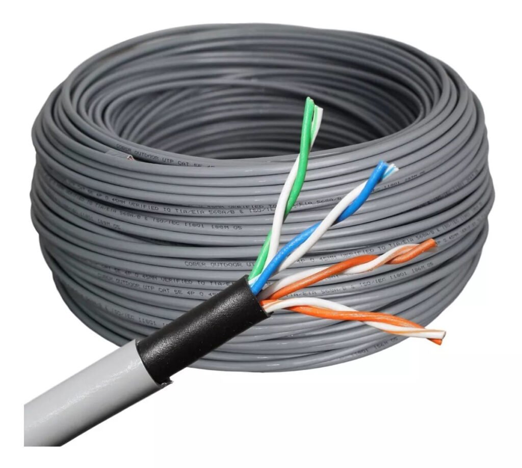
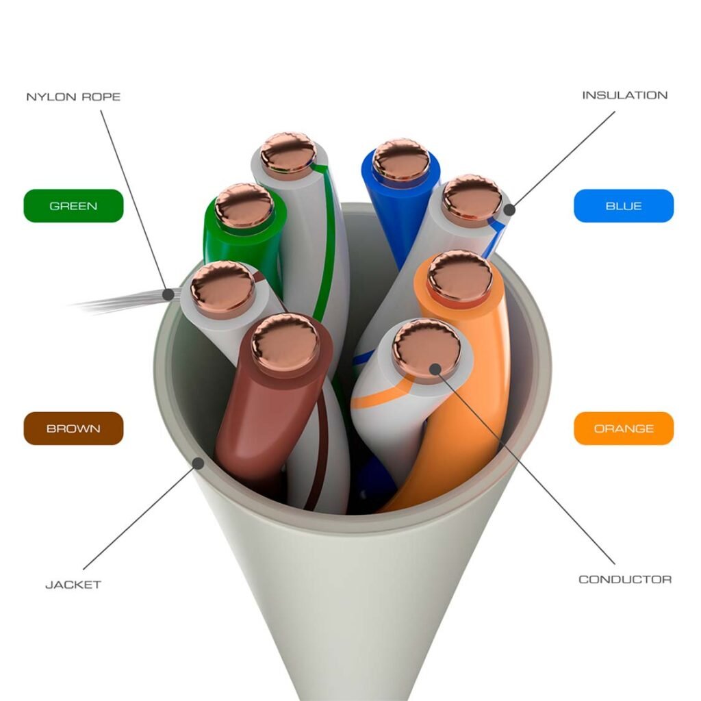
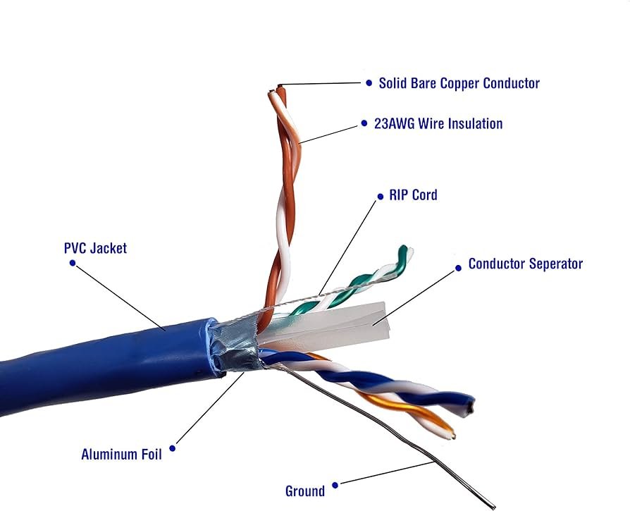
Unshielded twisted pair (UTP) cabling is the cabling specified for 100/1000BASE-T (100 Mbps/1Gbps speed) as well as 10GBASE-T (10Gbps speed) and is the predominant cabling system in use today. There are many types of twisted pair cabling available and the type to use depends on the needs of the networks. Twisted pair wiring consists of AWG 22–26 gauge copper wires twisted into color-coded pairs.
Each cable is individually insulated and enclosed as a group in a common jacket.
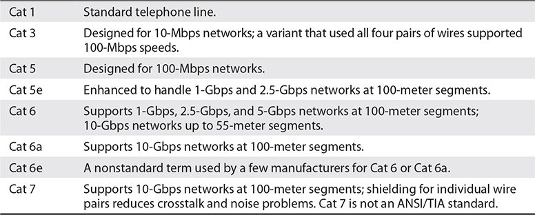
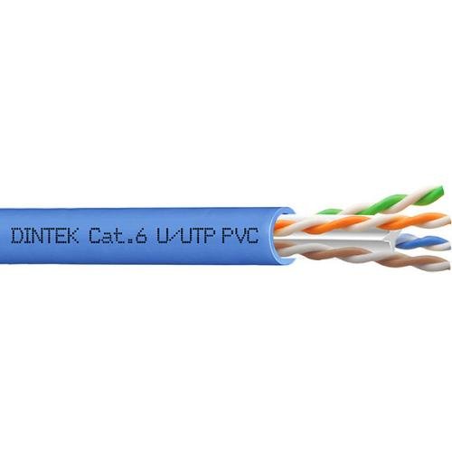
UTP cables come in categories that define the maximum speed at which data can be transferred, also called bandwidth. The main categories are described below:
Currently, most installers use Cat 5e, Cat 6, or Cat 6a cable. The cable must have the Category clearly marked as shown.
Shielded Twisted Pair Cable (STP Cable)
Shielded twisted pair (STP), as the name implies, consists of twisted pairs of cables surrounded by shielding to protect them from electromagnetic interference (EMI). STP is quite rare for 1Gbps networks, mainly because there is very little need for STP shielding.
It really only matters in places with excessive electronic noise, such as a workshop area with a lot of lights, electric motors, or other machinery that could cause problems for other cables. Some STP cables are rated to be installed directly underground without using raceways. These types of cables have a thicker jacket and some variety of waterproofing to make it suitable for outdoor or underground use without raceways.
Ethernet with Twisted Pair
The 10BASE-T (10 Mbps) and 100BASE-TX (100 Mbps) standards required two pairs of cables: one pair for sending and one pair for receiving. 10BASE-T ran on an older Cat version called Cat 3, but typically used at least one Cat 5 cable. 100BASE-TX required at least Cat 5 to work.
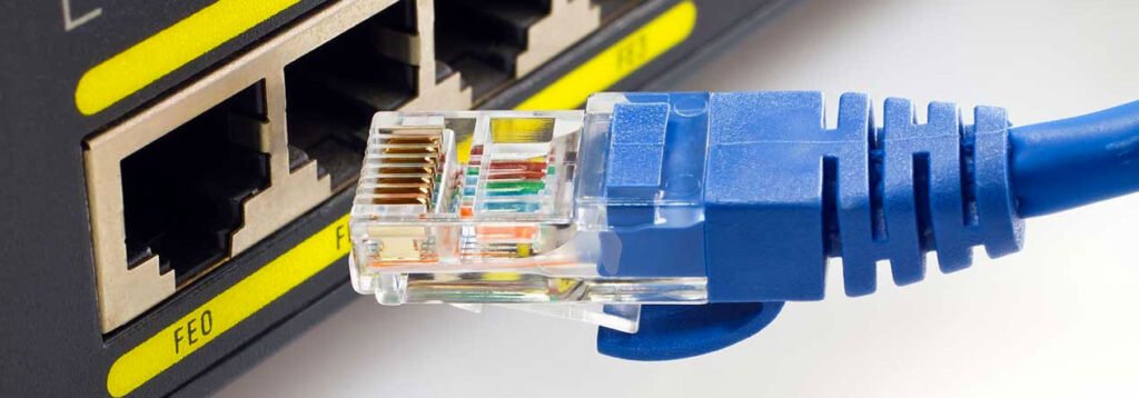
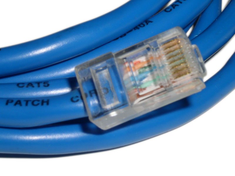
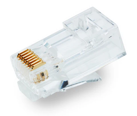
1000BASE-T (1 Gbps) requires all four pairs of cables in Cat 5e and higher, and 10GBASE-T requires all four pairs, but in Cat 6 or higher. These cables use a connector called an RJ45 connector. The RJ (registered jack) designation was invented by Ma Bell (the telephone company, for you young people) years ago and is still used today.
There are Cat levels for connectors and cables. You cannot use a Cat 5e RJ45 connector with a Cat 6 cable.
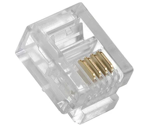
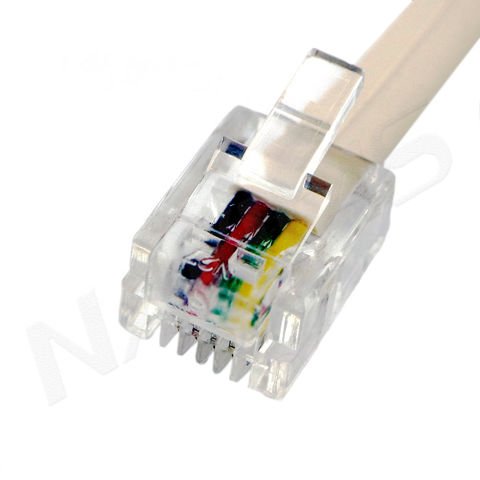
Currently, only two types of RJ connectors are used for networks: RJ11 and RJ45. RJ11 connects a traditional telephone to the telephone wall jack in your home. Supports up to two pairs of cables, although most telephone lines use only one pair. The other pair is used to support a second telephone line.
RJ11 connectors are primarily used for telephone Internet connections. RJ45 is the standard for UTP connectors. RJ45 has connections for up to four pairs and is visibly much wider than RJ11.
Plenum Versus PVC Cabling
Most workplace network cable installations run above the ceiling, down through walls, and often under floors. The space in the ceiling, under the floors, and in the walls through which the cable passes is called the plenum space.
The potential problem with this wiring passing through the plenum space is that the protective covering for the network cables, called a jacket, is made of plastic, and if the plastic gets hot enough, it generates smoke and harmful fumes.
Standard network cables typically use PVC (polyvinyl chloride) for the jacket, but PVC produces harmful fumes when burned. Fumes from cables burning in the plenum space can spread quickly throughout the building, so use a more flame-resistant cable in the plenum space.
Plenum grade cable is simply network cabling with a flame retardant jacket and is required for cables that run in the plenum space. Plenum-grade cable costs three to five times more than PVC, but you should use it whenever you install cable in a plenum space.
UTP Cable Color Coding"
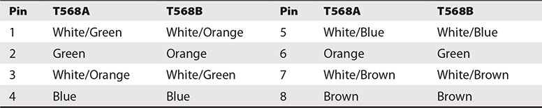
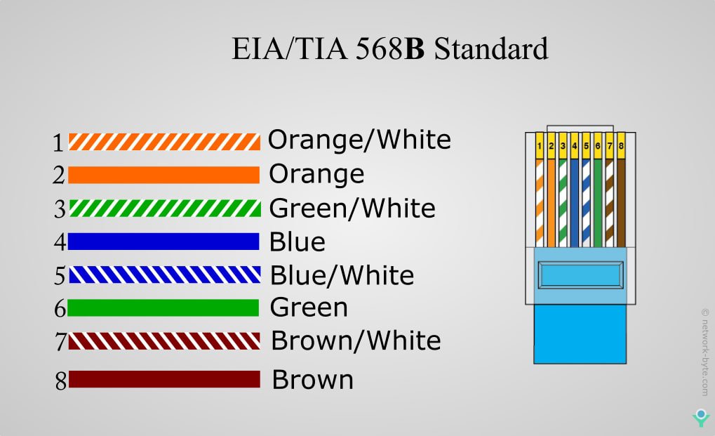
ANSI/TIA has two standards for connecting RJ45 connector to UTP cable: T568A and T568B. Both are acceptable. You don’t have to follow any standards as long as you use the same pairs at each end of the cable; However, you will make your life easier if you choose a standard. Make sure all your wiring uses the same standard and you will save yourself a lot of work in the end. The most important thing is that you make notes of the order you followed for the wiring in each RJ45 connector and keep records.
A number does not appear on each UTP cable, but rather each cable has a standardized color. Below we show the official ANSI/TIA standard color table for UTP.
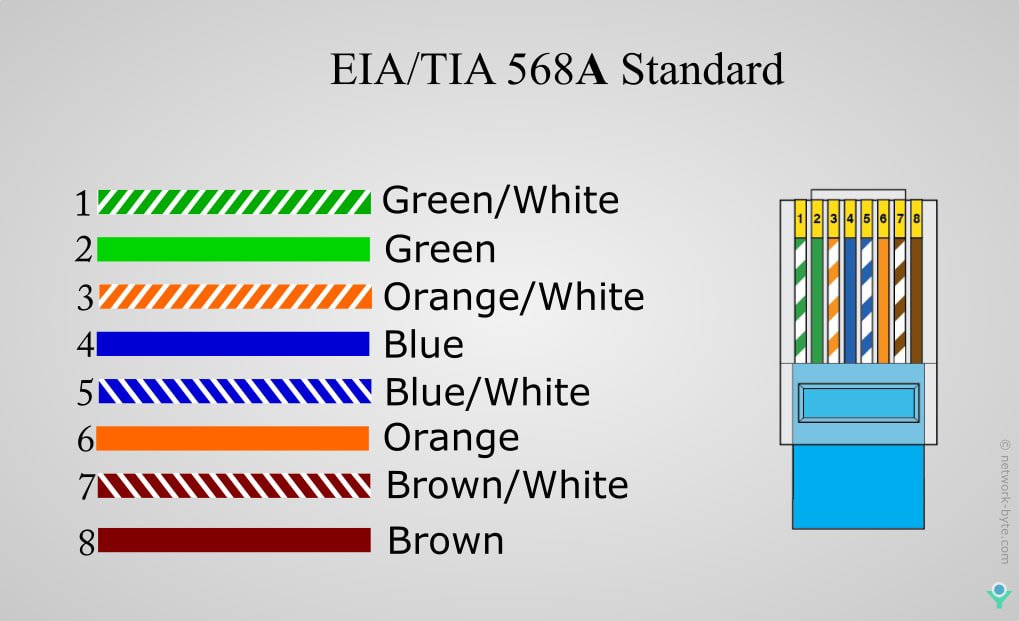
Below we show you this same information from the official ANSI/TIA standards for UPT Cable contained in the previous table. Here we can see it in a clearer, easier to understand way and we can also see very clearly the difference and similarity between both versions of those color codes.
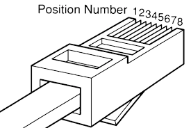
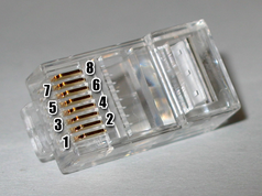
Below is the position of pins #1 and #8 on an RJ45 connector.
Alternative Ethernet Connections
UTP is very popular, but Ethernet, as well as other types of networks, can use alternative cabling that needs to be identified such as fiber optic cable and coaxial cable.
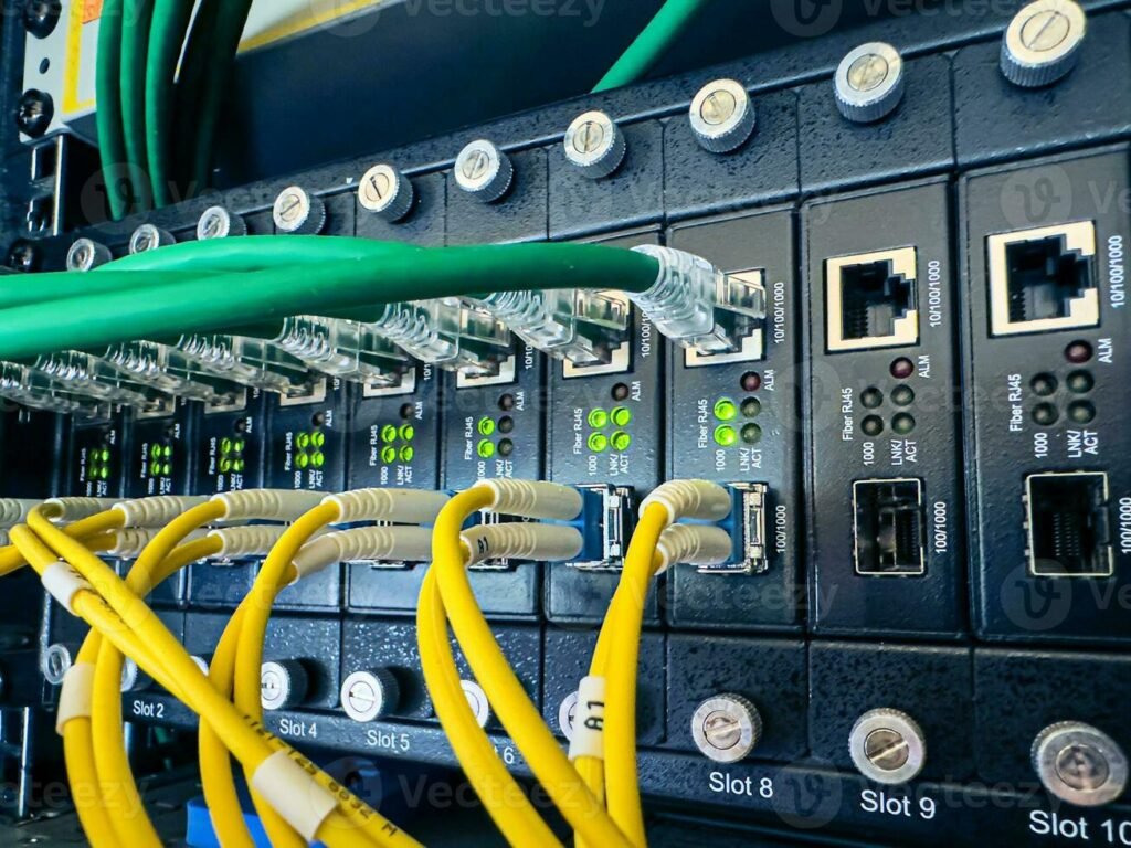
Fiber Optic
Fiber optic cable is a very efficient way to transmit Ethernet network frames. First, because it uses light instead of electricity, fiber optic cable is immune to electrical problems such as lightning, short circuits, and static. Second, fiber optic signals travel much further, 2,000 meters or more (compared to 100 meters for UTP).
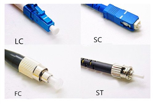
Many Ethernet fiber networks use 62.5/125 multimode fiber optic cable. All fiber Ethernet networks that use this type of cabling require two fiber strands (one for sending and one for receiving). Below we show three of the most common connectors used in fiber optic networks. The round connector on the left is called the straight tip or ST connector. The square-shaped center connector is called a subscriber connector or SC connector, and on the far right is a Lucent connector or LC connector.
Fiber optics are half-duplex, meaning data flows in only one direction, hence the need for two cables in a fiber installation. With older ST and SC connectors, two connectors are needed on each fiber connection. Newer connectors, such as LC, are designed to accommodate two fiber cables in one connector, a real space saver.
Light can be sent through a fiber optic cable as normal light or as laser light. Network technologies that use laser light use single-mode fiber optic cabling, which is why single-mode fiber optic cabling forms the backbone of the Internet.
There are about 100 different Ethernet fiber optic cabling standards, with names like 10GBASE-SR and 100GBASE-LR1. The main difference is the speed of the network. If you want to use fiber optic cabling, you need a fiber optic switch and fiber optic network cards.
Coaxial cable
Early versions of Ethernet ran over coaxial cable instead of UTP. While Ethernet standards using coaxial cable are long gone, coaxial cable lives on, primarily for cable modems and satellite connections.
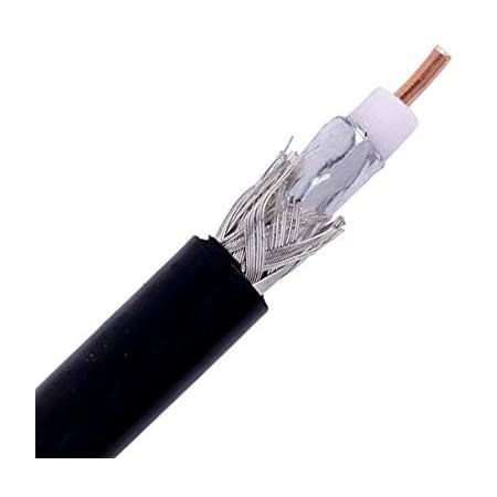
Coaxial cable consists of a central wire (core) surrounded by insulation. This in turn is covered with a braided cable shield. The central core actually carries the signal. The shield effectively eliminates external interference. Additionally, the entire cable is surrounded by a protective insulating jacket.
Coaxial cables are classified with an RG name. There are hundreds of RG ratings for coaxial, but the only two most used and common are RG-59 and RG-6. Both standards are rated by impedance, which is measured in ohms. (Impedance is the effective resistance to the flow of an alternating electric current through a cable.)
Both RG-6 and RG-59 have an impedance of 75 ohms. Your cable TV uses both coaxial cables, but RG-59 is thinner and does not carry data as far as RG-6. The RG rating is clearly marked on the cable.
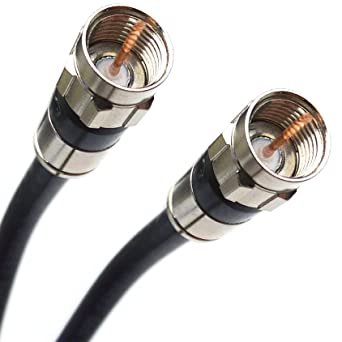
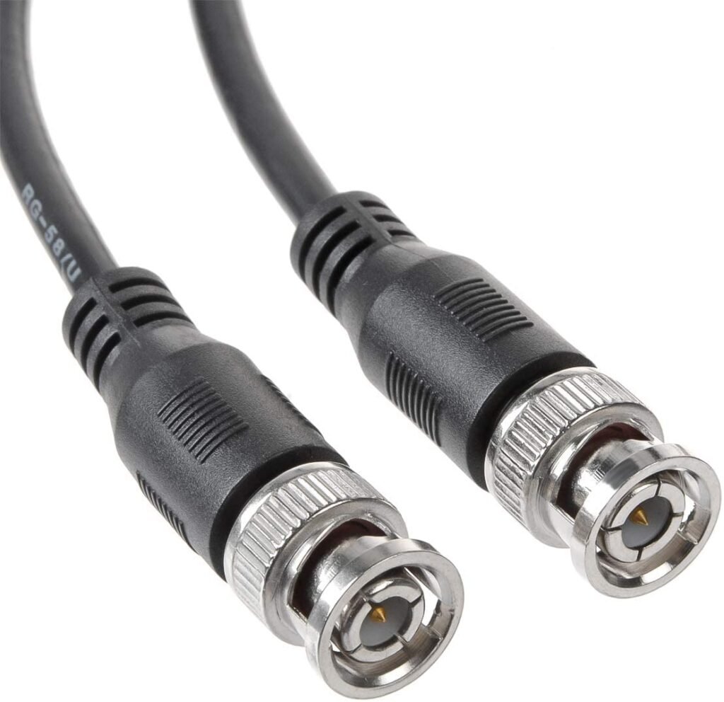
Coaxial cable uses a connector known as an F-type connector. You may already recognize this connector from the back of your cable modem or television. There is another type of connector called a BNC connector, but it is largely obsolete.
F-type connector
BNC-type connector
Local Area Networks (LAN)
A local area network (LAN) is a group of computers located physically close to each other, no more than a few hundred meters apart at most. A LAN can be in a single room, on a single floor, or in a single building.
You can set up a LAN in a small office/home office (SOHO) environment in several ways. The most common way (using wireless technology called Wi-Fi) completely eliminates cables. In another Post we will discuss this topic in detail.
Another option uses the building’s existing electrical grid for connectivity. This option, called Ethernet over Power, requires specialized jumpers that connect to power outlets.
Ethernet over Power has its place in the right situations, and recent innovations have brought speeds to nearly match Gigabit Ethernet. If you have a computer in a strange place where wireless doesn’t work and traditional cables can’t reach, try Ethernet over Power.
Structured Cabling
If you want a functional, reliable, real-world network, you need a solid understanding of a set of standards collectively called structured cabling. These standards, defined by ANSI/TIA, provide professional cable installers with detailed standards on every aspect of a wired network, from the type of cabling to use to standards for running cables in walls, even the position of plugs. wall.
The idea of structured cabling is to create a secure and reliable cabling infrastructure for all devices that may need interconnection. This certainly applies to computer networks, but also to telephone, video, and anything that might need low-power distributed cabling.
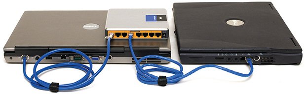
Challenges of Basic Ethernet LAN Setup
Previously in this same post we developed the idea of an Ethernet LAN in its most basic configuration: a switch, some UTP cable and some computers; in other words, a typical physical star network.
A good installation provides security, protecting the wiring from any physical damage and/or electrical interference. You must have extra hardware to organize and protect the wiring. Finally, the new and improved star network installation must also feature a cabling standard with the flexibility to allow the network to grow as it needs and then upgrade when the next network technology arrives.
Structured Cable Networks Components
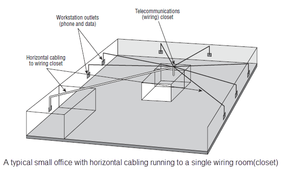
Successful implementation of a basic structured cabling network requires three essential ingredients: a telecommunications room, horizontal cabling, and a work area. Let’s focus on a typical office floor. All wiring runs from the individual workstations to a central location, the telecommunications room. The important thing is not the equipment that goes there (a switch or a telephone system). What matters is that all the cables are concentrated in this single area.
All cables run horizontally (for the most part) from the telecommunications room to the workstations. This wiring is properly called horizontal wiring. A single piece of installed horizontal wiring is called a run. At the opposite end of the horizontal wiring from the telecommunications room is the work area. The work area is usually simply an office or cubicle potentially containing a workstation and telephone.
Each of the three parts of a basic star network (the telecommunications room, the horizontal cabling, and the work areas) must follow a series of strict standards designed to ensure that the cabling system is reliable and easy to manage. The wiring standards established by ANSI/TIA allow technicians to make sound decisions about the equipment installed in the telecommunications room, horizontal cabling, and work area.
Horizontal Cabling
A horizontal cabling run is the cabling that runs more or less horizontally from a work area to the telecommunications room. In most networks, this cable is Cat 5e or higher UTP, but when you move to structured cabling, ANSI/TIA standards define a number of other aspects of the cable, such as the type of cables, the number of wire pairs , and fire classifications.
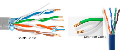
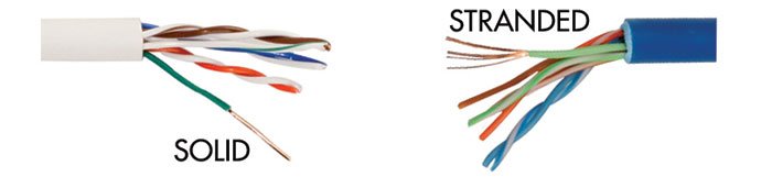
Solid core versus stranded core (wire or cable)
All UTP cables come in one of two types: solid core or stranded core. Each cable in solid core UTP uses a single solid wire. With a braided core, each cable is actually a bundle of small wire strands. Each of these types of cables has its advantages and disadvantages. The solid core is a better conductor, but it is rigid and will break if handled too often or too roughly. The stranded core is not as good a conductor, but will withstand substantial handling without breaking.
ANSI/TIA specifies that horizontal cabling must always be solid core. Remember, this wiring goes into your walls and ceilings, safe from shoes (exposed wires running across the floor are waiting for someone to trip over them. Simply moving and stepping on the wiring will, over time, cause a wire to fail. due to cable breakage or RJ45 connectors tearing off cable ends) and vacuum cleaners.
Ceilings and walls allow you to take advantage of the better conductivity of the solid core without the risk of damaging the cable.
The Telecommunications Room
The telecommunications room is the heart of the basic star. This room is where all the horizontal sections of all the work areas come together. The concentration of all this equipment in one place makes the telecommunications room potentially one of the messiest parts of the basic star.
Even if you do a nice, tidy job of organizing cables when they are first installed, networks change over time. People move computers, new work areas are added, network topologies are added or improved, etc. Unless some form of organization is imposed, this conglomeration of equipment and cables breaks down into a nightmarish mess.
Fortunately, ANSI/TIA structured cabling standards define the use of specialized components in the telecommunications room that make organization easier. In fact, it would be fair to say that there are too many options.
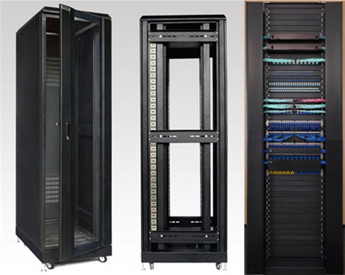
Equipment Racks
The central component of each telecommunications room is one or more equipment racks. An equipment rack provides a secure and stable platform for all the different hardware components. All equipment racks are 19 inches wide, but range in height from two- to three-foot-tall models that bolt to a wall to the more popular floor-to-ceiling models.
You can mount almost any network hardware component in a rack. All manufacturers make switches that mount to a rack with a few screws. These switches are available with a wide variety of ports and capacities. There are even rack-mounted servers, complete with slide-out keyboards and rack-mounted uninterruptible power supplies (UPS) to power the equipment.
All rack-mounted equipment uses a height measurement known simply as RU. One RU measures 1.75 inches. A device that fits into a 1.75-inch space is called a 1RU; a device designed for a 3.5-inch footprint is a 2RU; and a device that occupies a space of 7 inches is called 4RU. Most rack-mounted devices are 1RU, 2RU, or 4RU.
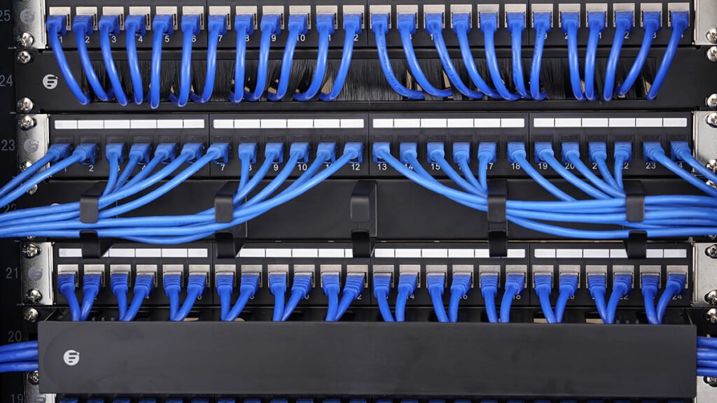
Patch Panels and Cables
Ideally, once the horizontal wiring is installed, you should never move it. As you know, UTP horizontal cabling has a solid core, which makes it quite rigid. Solid core cables can withstand some rearranging, but if you insert a bundle of solid core cables directly into your switches, every time you move a cable to a different port on the switch, or move the switch itself, you will push the cable. In reality, without moving a solid core cable many times, it will break or split and consequently affect the network connection.
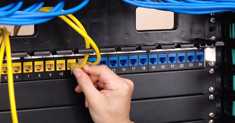
This problem can be easily avoided by using a patch panel. A patch panel is simply a box with a row of female connectors (ports) on the front and permanent connections on the back, to which horizontal cables are connected.
Patch panels not only prevent horizontal wiring from moving, but they represent an effective way to organize cables by placing labels and identifying each cable and thus saving headaches and time when there are network failures.
Patch panels can contain UTP, STP, or fiber ports, and some manufacturers combine several different types on the same patch panel. Panels are available with 8, 12, 24, 48 or even more ports.
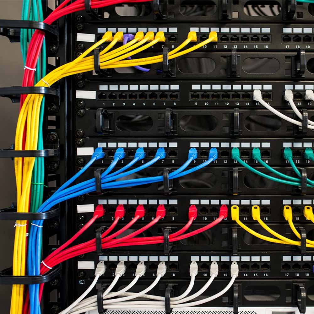
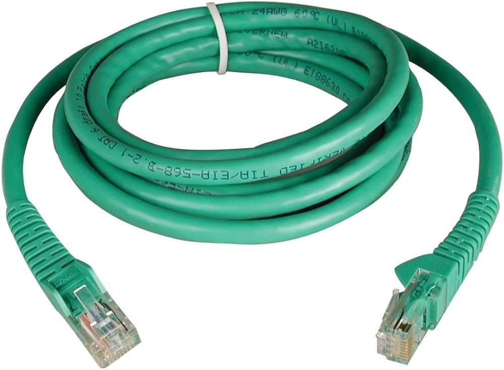
Once you have installed the patch panel, you will need to connect the ports to the switch using patch cables. Patch cables are short UTP cables (typically two to five feet). The patch cords use stranded wires rather than solid wires, so they can tolerate much more handling.
Purchasing pre-made patch cables allows you to use different colored cables for easy cable organization (using a different color for each department in a company). Most pre-made patch cables also come with a reinforced (sleeved) connector specially designed to withstand multiple insertions and removals.
Making your own Patch Cables
Although most people prefer to simply purchase pre-made patch cables, making your own is quite easy. To create your own, use a stranded UTP cable that matches the Cat level of your horizontal cabling. Stranded cable also requires specific assembly, so do not use methods designed for solid cables. Assembling UTP cables is fairly simple, although doing it well requires some practice.
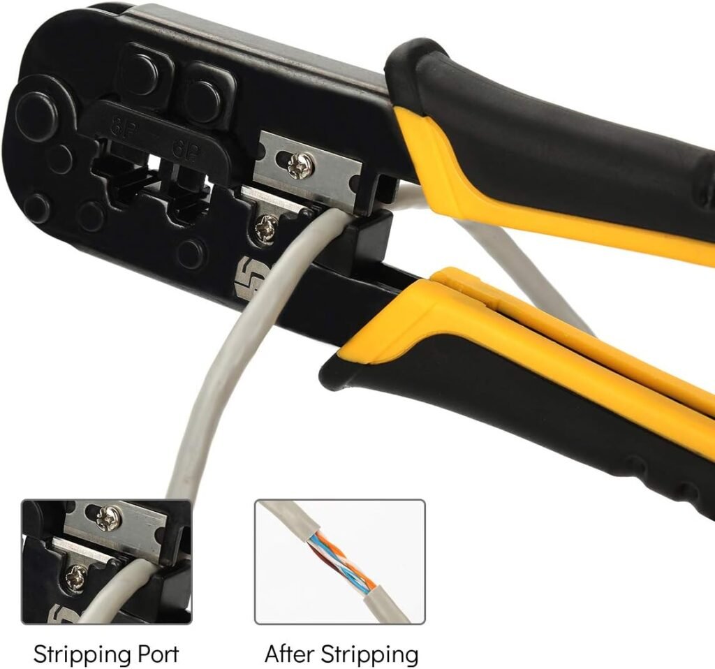
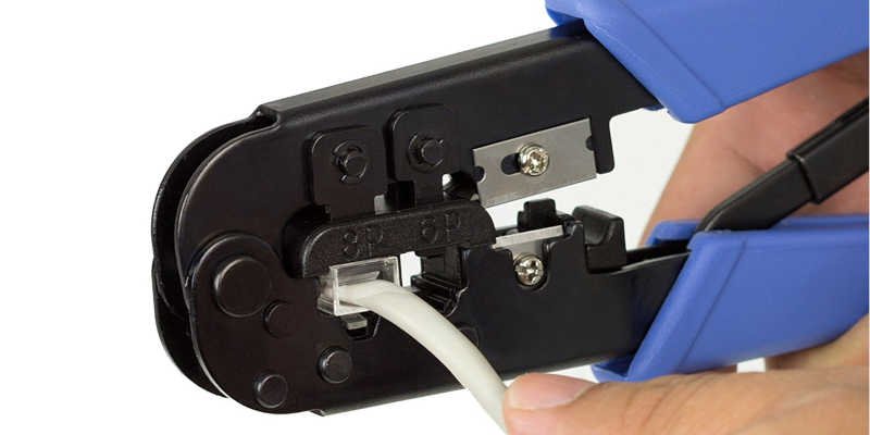
The following figure shows the main tool for assembly: pliers with built-in wire strippers and cable cutters. Naturally, professional cable installers also have a wide variety of additional tools including cable testing.
Crimping an RJ45 onto a UTP cable
Here are the steps for properly crimping an RJ45 onto a UTP cable.
Cut the cable squarely with scissors or RJ45 pliers.
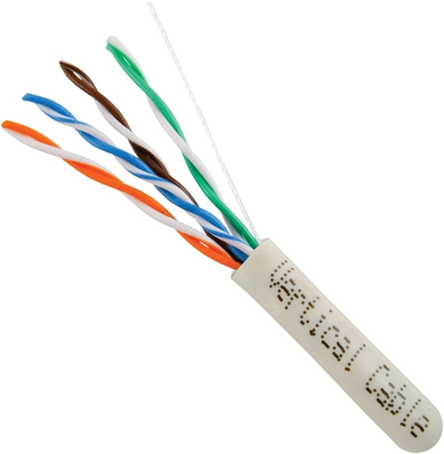
2. Peel half an inch of plastic covering from the end of the cable. (The additional white thread(s) that are barely noticeable along with the twisted wire pairs are called marker threads or ripcord. The Kevlar threads strengthen the cable and allow installers to easily tear off the sheath.)
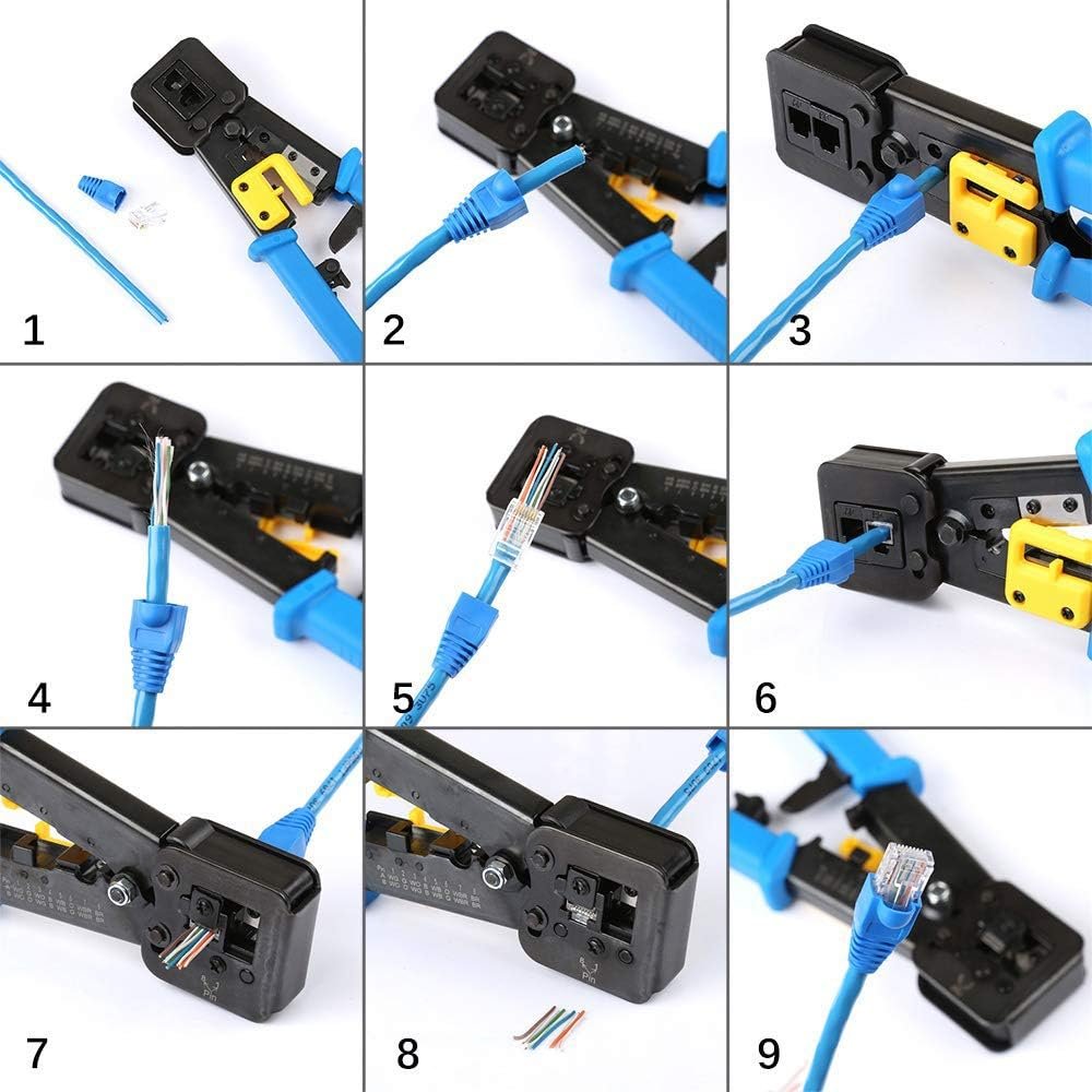
3. Slowly and carefully insert each individual wire into the correct location in accordance with ANSI/TIA 568A or B (this time B). Untangle the cable as little as possible. To do this, use the tweezers for this purpose from the beginning, that is, from stripping or removing the outer insulation of the UTP cable.
Below you can see in images the complete assembly process of a UTP cable in an RJ45 connector, ordering the cables according to the aforementioned standard.
4. At this point you can see step 8 and 9 of the previous process in more detail. Insert the RJ45 connector with the UTP cable inside, into the RJ45 receptacle of the pliers and press. You don’t have to worry if you press too hard; The tweezers have a stop to prevent you from applying too much pressure.
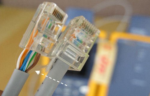
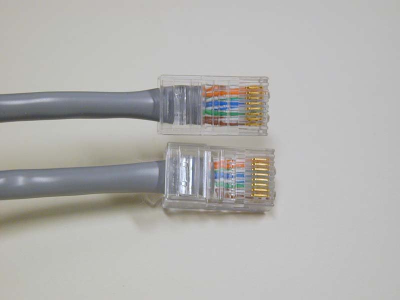
The figure shows a cable that is very well assembled and another that is not. Note how the plastic cover should fit into the RJ45 connector.
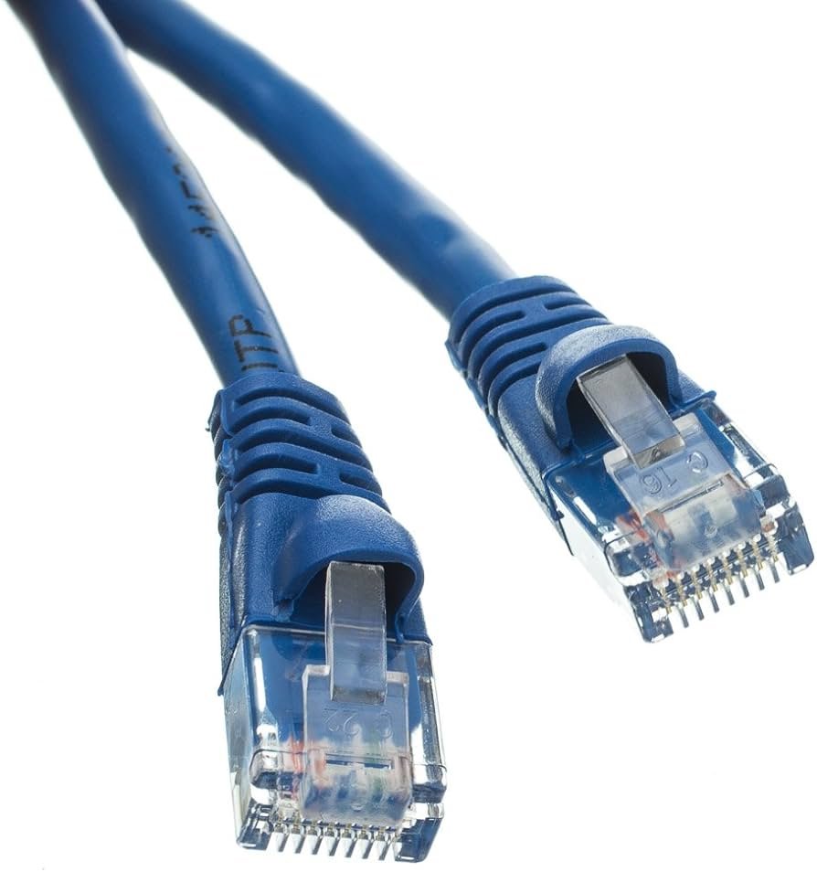
A good patch cable should include a boot. The UTP cable must be inserted into the boots before assembling the cable and the RJ45 connector, or in other words, before assembling in question, you must slide the boots over the patch cable.
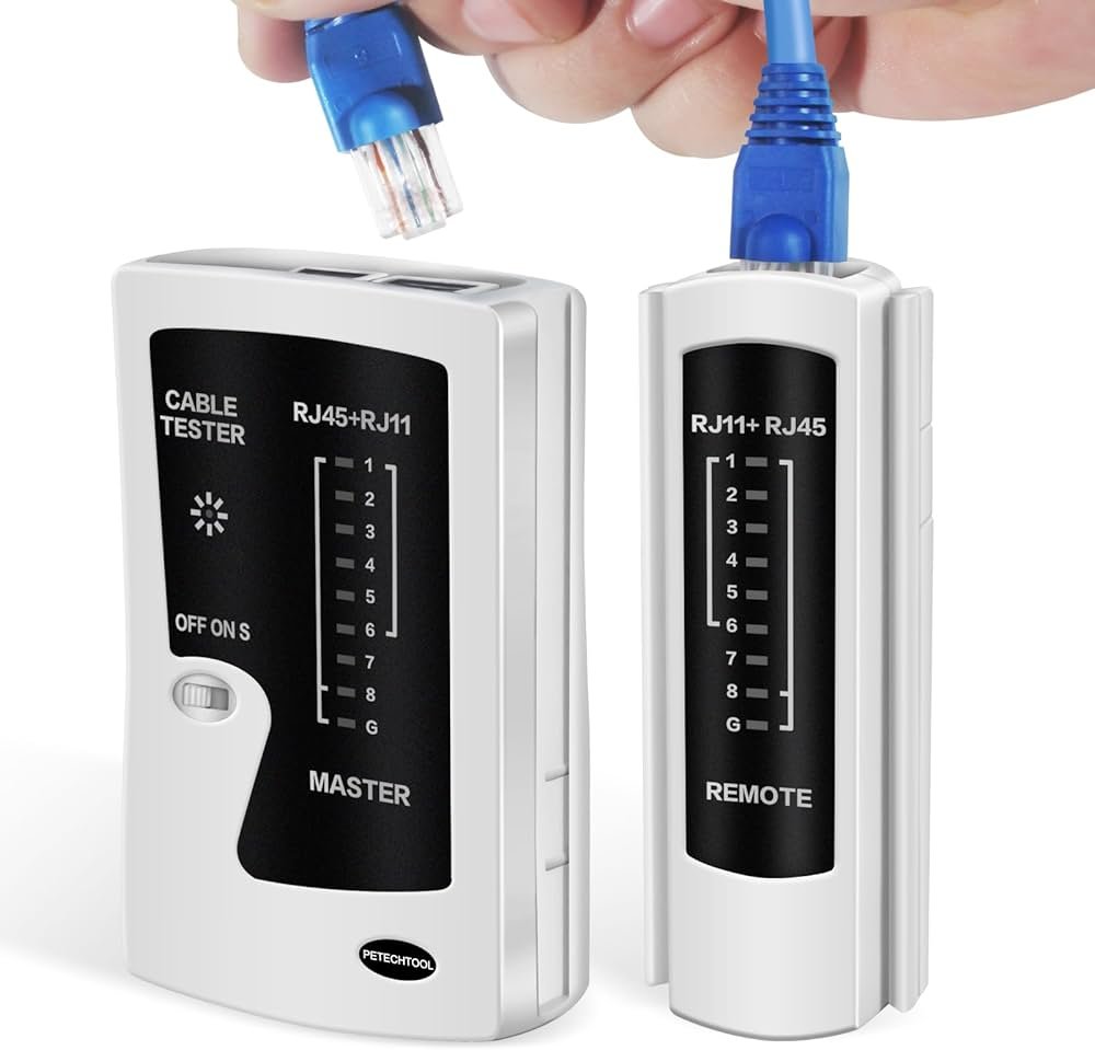
UTP Cable Test
After assembling a UTP cable, you should test it to make sure it is working properly. For this purpose, a handy cable tester, available at any good electronics store, is used to verify that all the individual cables are connected in their correct location.
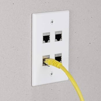
Work Area
From a cabling standpoint, a workspace is nothing more than a wall outlet that serves as a termination point for horizontal network cables, a convenient insertion point for a workstation and a telephone.
In practice, of course, the terms work area include the office or the cubicle. A wall outlet consists of one or two female plugs to accept the cord, a mounting bracket, and a faceplate. Connect the workstation to the wall outlet with a patch cord.
The last step is to plug the workstation into the wall outlet. Again, most people use a patch cord. Its stranded cabling resists abuse caused by moving equipment, not to mention the occasional kicking people.
The work area may be the simplest part of the structured cabling system, but it is also the source of most network failures. When a user cannot access the network and suspects a broken cable, the first place to look is the work area.
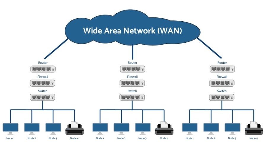
Expanding the Reach of Computer Networks
A wide area network (WAN) is an extended group of computers connected using long-distance technologies. LANs connect to a WAN with a box called a router. The best example of WAN is the Internet.
Computer Networks: The Pulse of a Connected World and the Future of Communication
In a world where information is power, Computer Networks are the backbone of our digital age. They do more than just connect devices—they drive globalization, innovation, and automation to unprecedented levels. From homes to the largest corporations, networks enable instant communication, massive data storage, and the integration of advanced technologies like Artificial Intelligence, the Internet of Things (IoT), and Cloud Computing.
But the future promises even more: faster, safer, and more efficient networks. With the advent of 6G, Quantum Computing, and Hyperconnectivity, the potential of networks is expanding into uncharted territories, transforming industries, economies, and everyday life. Those who master networking technology will master the future. The Revolution Doesn’t Stop, and Computer Networks are the Engine Driving it Forward.